Commissioning
Vertiv/ESS commissioners maximize your return by delivering improved availability, enhanced safety, increased efficiency, and reduced operational costs.
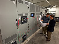
Vertiv/ESS commissioners maximize your return by delivering improved availability, enhanced safety, increased efficiency, and reduced operational costs.
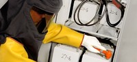
To prevent any damage, we will help you develop a maintenance schedule that is based on your equipment, voltage, and ambient conditions.

IT centric services supporting software, hardware, and network communications.
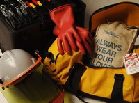
Services and assessments covering a broad scope of testing, studies, and training.

Obtain the parts you need, when you need them, with same day local customer pickup or same day shipping.